Sankey of Order Flow from Clients to Venues
Known issues
Some chart features have known issues in the current release. See Known issues.
This walkthrough draws order flow from 2 client types to 2 venues as ribbons, answering "Where does each client type's flow go?"
Prerequisites
- Editor mode: click once on the screen, then press Ctrl+d. The AMIDB Shell Tool and the gallery are used as in the quickstart.
- Data: the example data that stage 1 creates. To use a table of your own instead, see With your own data.
1. Create the example data
The chart reads a table in the Center, so create the table first.
- Select Dashboard -> AMIDB Shell Tool....
-
Run:
-
Check that the lower pane shows the 4 node rows, and that
SELECT * FROM ChartDemoFlowLinks;shows the 6 link rows.
The template computes no layout, so 2 tables hold it:
ChartDemoFlowNodes: one row per node, with its stage, its bottom and top on the vertical scale, and a color numberChartDemoFlowLinks: 2 rows per ribbon, sharing aRibbonid and naming the stage the ribbon leaves
In the links table, Offset is how far across to the next stage a row sits, from 0.05 just right of the node to 0.95 just left of the next one, and Top and Bottom are the ribbon's edges at that point.
The stages are numbered so that their alphabetical order is their left-to-right order.
2. Create the chart
The gallery creates a datamodel that reads the table, then places the chart.
- Select Windows -> New Window, then the edit button on
Blank1, then "Create Table / Visualization / Form". - Select "AMI (__AMI)", then "Next >>".
- Select the "USER" tile
ChartDemoFlowNodes, then hold Ctrl and selectChartDemoFlowLinks. The preview shows a tab for each table. Select "Next >>". The datamodel the wizard creates is nameddatamodel, and its query creates both tables. - Select "Test (alt+enter)", then "Next >>".
- The wizard asks "The chosen datamodel contains multiple tables. Please choose a table." Choose
ChartDemoFlowNodes, then select "Choose table". - Select the "Flow" tab, then the "Sankey" tile.
-
Set the fields below the tiles:
Field Value "Node column:" Stage"Node bottom:" Bottom"Node top:" Top"Node colour:" Clr"Node label:" Node"Links table:" ChartDemoFlowLinks"Link column:" Stage"Link x offset:" Offset"Ribbon top:" Top"Ribbon bottom:" Bottom"Ribbon id:" Ribbon"Source colour:" SrcClr"Target colour:" TgtClr -
Select "Finish".
- Check that the window shows 2 nodes under "1 Clients" and 2 under "2 Venues", joined by 3 ribbons, the middle one curving from "Institutional" down to "Lit".
Result
Retail flow, 40, all goes to Lit; Institutional flow, 60, splits 30 to Lit and 30 to Dark. Each ribbon shades from its source node's color to its target's.
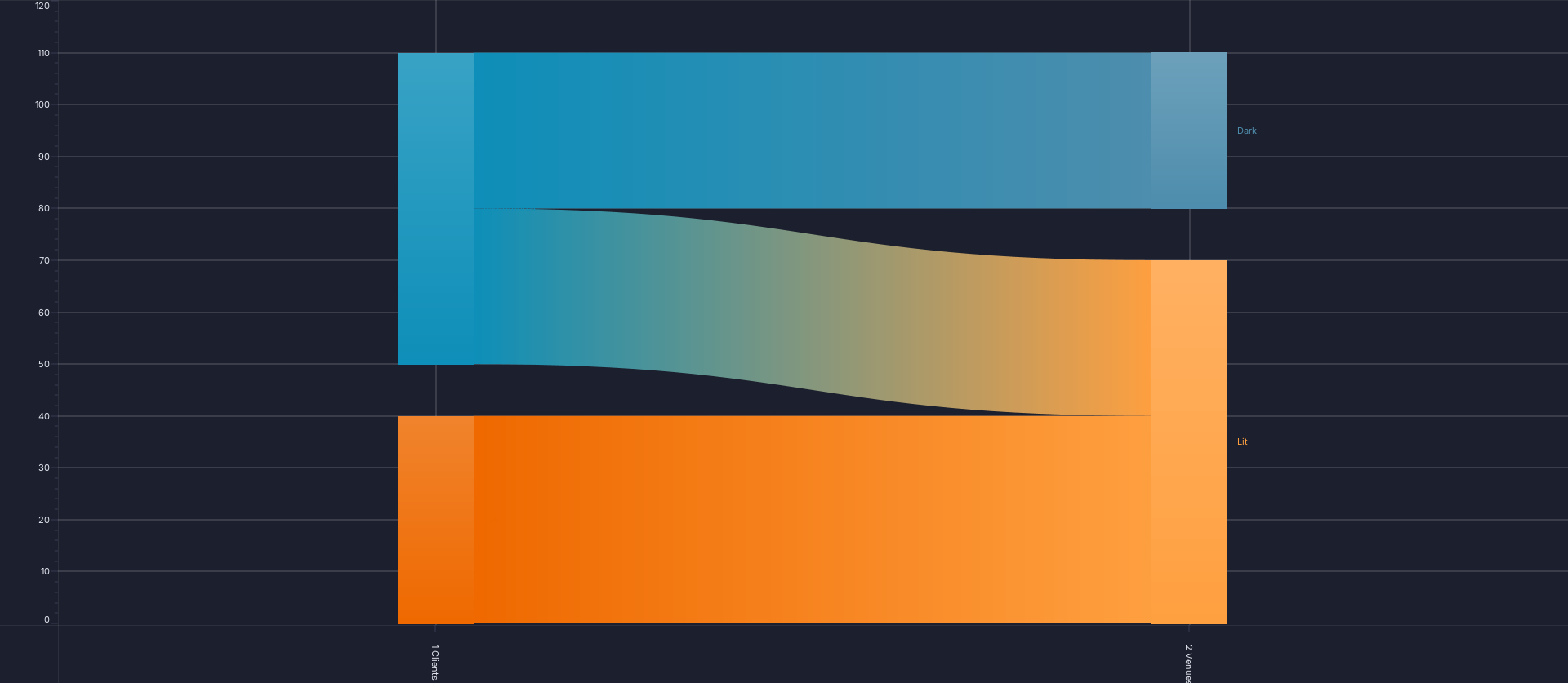
The chart's own PNG export, from AmiScript toImagePng; see Chart type walkthroughs.
To check without looking, read the render stats: session.getDevTools().getAllRenderStats() in the AMIDB Shell Tool, with "Run on this web session" selected (see Running a script), or web_debug op=panelRenderStats over MCP. The "Nodes" layer reports Rows 4, and the "Ribbons" layer Rows 6 and "3 groups", each with an empty Problem.
With your own data
The chart needs 2 tables: one row per node with its stage and its bottom and top, and one row per link with its ribbon's top and bottom at each end. The template computes no positions, so the datamodel must supply every one: these charts suit data that already carries its positions, or a query written for one fixed layout. To filter rows, or to total raw rows first, see Using your own data.
Over MCP
An agent builds the same chart from the same table. Connecting an agent is covered in the AI section; the tools are on Building charts over MCP.
-
Create the datamodel with
web_executeop=importDatamodeland thisdmJson, then run it once withop=initDatamodelSchemaanddmNameChartDemoFlow: -
Create the chart:
-
Run the datamodel again with
web_executeop=executeDatamodel,dmNameChartDemoFlow. A chart created over MCP can stay empty until its datamodel runs again, with its axes at 0-100. - Confirm that every layer reports the rows above and an empty
Problem: runweb_debugop=panelRenderStats.
The call is web_create_chart_from_template, on the datamodel ChartDemoFlow, whose query creates both tables as Nodes and Links.
A Sankey created over MCP draws its ribbons half a stage to the left of one created in the gallery from the same rows: with the offsets above, each ribbon spans its source stage instead of the gap. Over MCP, move every offset half a stage on before creating the chart, with UPDATE ChartDemoFlowLinks SET Offset = Offset + 0.5; in the AMIDB Shell Tool, so that they run from 0.55 to 1.45.
Removing the example
Remove the chart, then its datamodel, then the table, so that the next walkthrough can reuse the names:
- Close the chart's window with its close button, and select "Delete" when asked whether to delete the panel.
- Select Dashboard -> Data Modeler..., expand "Datamodels", right-click the chart's datamodel,
datamodel, and select "Delete Datamodel", then "Yes". - Run
DROP TABLE ChartDemoFlowNodes; DROP TABLE ChartDemoFlowLinks;in the AMIDB Shell Tool. - Check that
SELECT * FROM ChartDemoFlowNodes;reportsUnknown table: ChartDemoFlowNodes.
Over MCP, delete the chart with web_danger op=deletePanel, then the datamodel with op=deleteDatamodel, dmName ChartDemoFlow, and drop the tables as in step 3. deleteDatamodel refuses a datamodel that has been committed; delete that one in the Data Modeler as in step 2. See Removing an agent's chart.